Driver in a Mass Loaded Transmission Line - Acoustic and Electrical Response
by Martin J. King
e-mail MJKing57@aol.com
Copyright 2009 by Martin J. King. All Rights Reserved.
Unit and Constant Definition
Part 1 : Thiele-Small Consistent Calculation
Abbreviated User Input (Edit This Section and Input the Parameters for the System to be Analyzed)
Driver Thiele / Small Parameters : Markaudio Alpair 10 Gold FR
Enclosure Geometry Definition : Model of Internal Air Volume
(Driver Internal Distance From Top < Height)
(Port Internal Distance From Top < Height)
(Internal Area of the Top End, z = 0)
(Internal Area of the Bottom End, z = L)
(Stuffing density : 0 lb/ft3 < D < 1 lb/ft3)
(Inside Radius of the Port)
(Input Power) Applied Voltage Reference --->
End of Abbreviated User Input
Pre Formated Geometry and Stuffing Location Input (Only Edit Details Below to Change Defaults)
(0 lb/ft3 < D < 1 lb/ft3)
(Driver ---> Top of Enclosure)
Open Section of Enclosure
(Driver ---> Port Position)
Bottom Section of Enclosure
(Port Position ---> Bottom of Enclosure)
Port Section of Enclosure
(Port Inside ---> Port Outside)
End of Pre Formatted Default Input
Resulting Acoustic Impedance for the Enclosure
Velocity at the Terminus of the ML TL for a 1 m/sec Excitation at the Driver Position
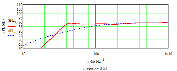
Far Field ML TL System and Infinite Baffle Sound Pressure Level Responses
Woofer and Terminus Far Field Sound Pressure Level Responses
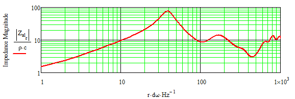
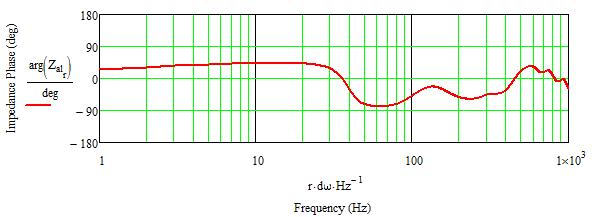
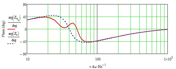
ML TL System and Infinite Baffle Impedance
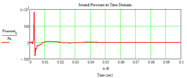
System Time Response for an Impulse Input
Port Air Velocity (should be < 10 m/sec / 344 m/sec = 0.03)
Part 2 : Detailed SPL Response Calculation
Calculation Includes :
Position of Driver and Port on the Baffle.
Baffle Step Defraction for the Driver and the Port.
Room Reflections for the Driver and the Port.
Baffle Coordinate System :
Origin is the lower left corner of the front baffle
y = horizontal direction
z = vertical direction
The variables num_r, n_drv, and n_mth control the number of simple sources that are used in the
calculations. Increasing each will improve accuracy at the expense of longer calculation times.
Increase each variable until plotted SPL stops changing at which point the solution has converged.
(Front Baffle Distance from Rear Wall > Depth of Enclosure)
(Front Baffle Distance from Side Wall)
(Rotation Towards Room Center)
(Floor to Ceiling Distance)
(Height from Floor to Bottom Edge of Front Baffle)
(Number of Points per Unit Length of Baffle Edge)
(Driver Center y Coordinate)
(Driver Center z Coordinate)
(Number of Points Across Diameter)
(Port Center y Coordinate)
(Port Center z Coordinate)
(Number of Points Across Diameter)
(0 = Front Baffle Port, 1 = Rear Baffle Port)
Listening Position (Default Location is at 1 m Distance Along the Driver's Axis)
(Listening Position Relative to Speaker)
(Calculation Radius, Effective Radius is Greater if yp is Changed from Default)
(0 deg is along the Driver's Axis, -80 deg < q < 80 deg)
(Default Height is Equal to Driver Height)
(Listening Position Relative to the Room Corner)
(Default Height is Equal to Driver Height)
(0 = hardwood or concrete, 1 = carpeted)
Refective Surface Selections (if 1 reflective surface is included, if 0 reflective surface is removed)
Circular Driver and Circular Mouth Simple Source Pattern with Baffle Edge Outline
Red sources represent the driver.
Blue sources represent the port.
Black outline represents the baffle edge.
Origin is at the bottom front left corner of the enclosure.
<---- Change value of "axis" to rescale plots
Room Corner is the Origin
Side View - looking out from side wall
Front View - looking towards rear wall
Top View - looking down from ceiling
Plotted Baffle Step and Reflection SPL Response for the Circular Driver Source
Plotted Baffle Step and Reflection SPL Response for the Circular Port Source
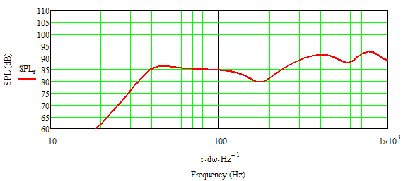
Plotted SPL Response for the System
Part 3 : Baffle Step Correction Circuit Design
Input Center Frequency of the Baffle Step and the desired dB of Attenuation.
<--- Input Center Frequency
<--- Input dB of Attenuation
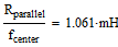
Calculated Component Values
User Assigned Component Values
Based on Calculated Values at Left
Plotted Corrected SPL Response for the System
ML TL Corrected System and Infinite Baffle Impedance
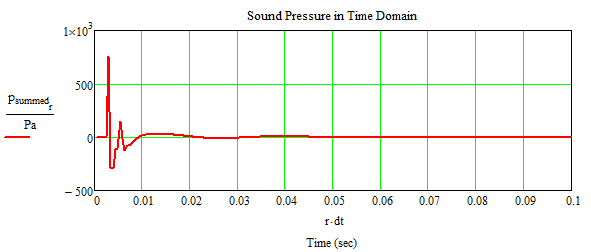
System Time Response for an Impulse Input